Monday, June 4, 2012

Competition Results


The final design required side panels for affixing the number to the car. This is shown in the figures below. The day of the competition was sunny, however when clouds did cover the sun slightly, it significantly altered the performance of all cars. Battery packs did not need to be used for any of the cars, the sunlight was sufficient. The junior division of the competition consisted of over 130 teams from elementary and middle schools in the area. The open division consisted of five teams registered from Drexel, and one or two other teams that registered the day of the event. Our car performed exceedingly well beating all other cars by a hefty margin. The first race shown is the first heat of the open division, and the second is the final heat of the open division with the winners of the junior division.

Figure 1: Final design with sidepanels, orthogonal view.  

Figure 2: Final design with sidepanels and payload, side view. 

Figure 3: Final design with payload, posterior view. 
Photo 1: Team Lucky 13 at the Northeast Regional Junior Solar Sprint Competition.  *

Photo 2: Preparing the solar car for the Open Division race heat by attaching the payload, solar panel, and guidewire.  *
*

*

Photo 3: Winners of the Junior Solar Sprint Open Division.  *

*: Photographs and videos courtesy of Rachel Cory


Lucky 13 in Action

Attached below is simply a basic demonstration of our solar car.  We tested it on the carpet inside our building, but even the small amount of sunlight passing through the windows was strong enough to power it until it reached the shade.  Also, the car accelerated at a noticeable rate.  So, we had rather high hopes for the competition.  We also tested the car on the patio of the Bossone Engineering Center.  Our vehicle actually accelerated at a rate far greater than we had originally assumed.  Needless to say, our car came out of the test somewhat damaged, but we managed to fix it rather easily with an even better structure supporting the solar panel.


Tuesday, May 29, 2012

Completion

Heading into Week 9, we have a mechanically and electronically complete model solar vehicle.  We would say it's fully complete, but it's missing one component that's required for the competition and aesthetics: the side panels.  Besides that, however, the car has been tested with the motor and solar panel attached and it is fully functional.  The weather forecast for the day of the competition is predicted to be rather cloudy with a chance of thunderstorms.  So, we decided to use the larger motor that seemed to generate greater torque but also had less sensitivity to the sun.  We figured that if it's sunny enough, we'll have an altogether faster car, but if the forecast holds up, we'll be forced to use the AA battery pack that we recently purchased anyway.

There weren't really any "problems" with the car when it was tested.  There were a few, small errors that can be easily adjusted, however.  For example, one of the front wheels would not securely remain attached to the axle, so we simply super-glued it on.  Also, the larger motor did not come with a mounting bracket as the first, smaller one did.  The piece of sticky foam that came with the larger motor does not securely hold it in place which causes the gear transmission to fall out of place as well.  Therefore, the motor too will most likely be glued in place to prevent its gear from becoming disconnected from the axle gear.  This way, we can prevent any unnecessary loss of torque.  Finally, as a point of reference, we would like to mention that in order to make the car go forward, the black wire must be attached to the front lead of the motor.

All in all, the entire project itself was a success regardless of the results of the upcoming race.  We've managed to model, design, and construct a very simple, miniature solar vehicle that harnesses the sun's energy and transform it into mechanical energy through the motor and wheels.  Now, all we have to do is hope it's good enough for the upcoming race.

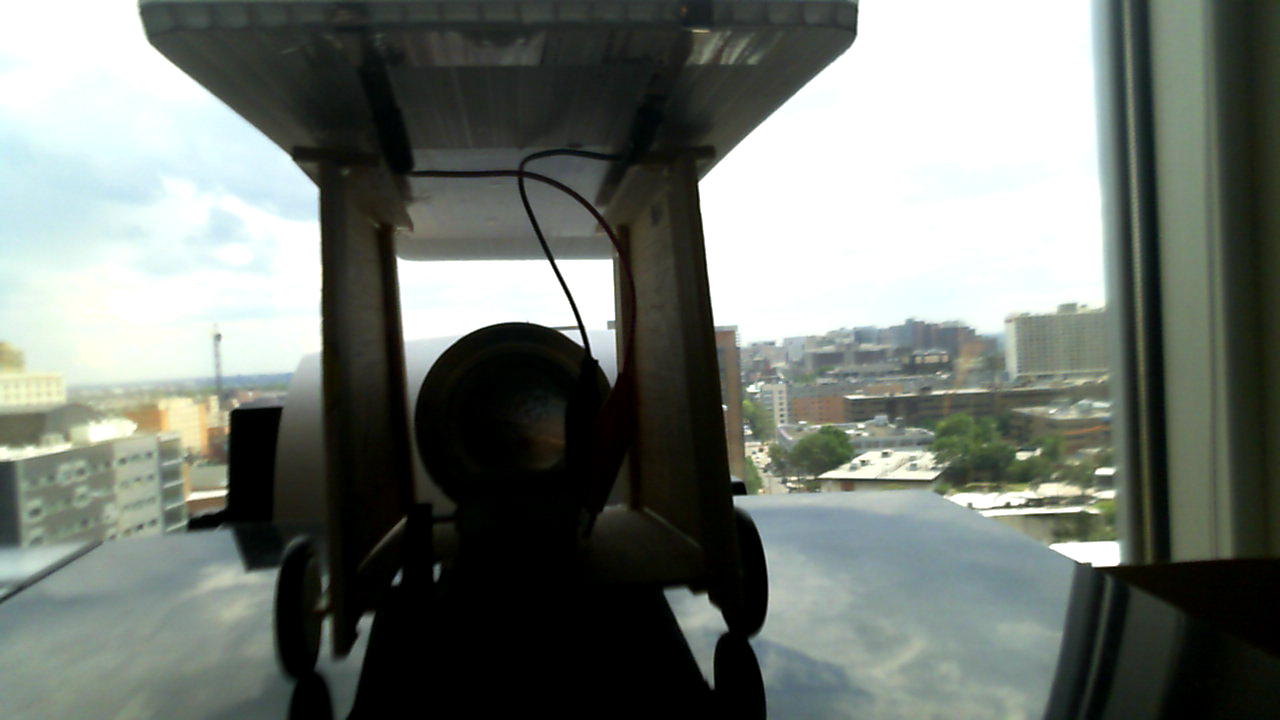
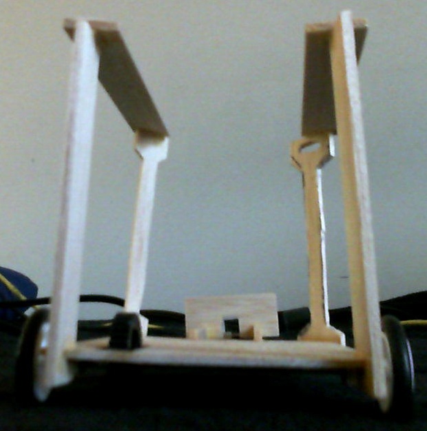
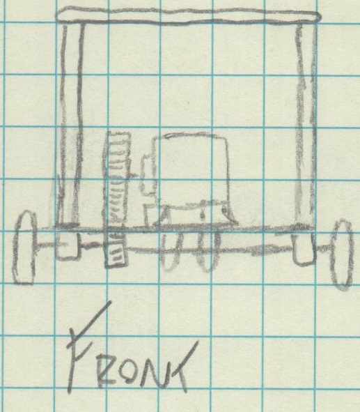
Below are simply more images of our solar car, but in its nearly final form with the motor and solar panel fully attached to each other and the car.

Figure 1: Solar car with motor and panel, front view.  [1]


Figure 2: Solar car with motor and panel, left side view.  [2]


Figure 3: Solar car with motor and panel, right side view.  [3]


Tuesday, May 22, 2012

CAR

Our solar car is nearing completion.  As seen in the figures below, the entire chassis is assembled, and the solar panel has been integrated into the body as well.
Using our models, we determined that the optimal gear ratio would be about 5 or 6, but due to the inhibiting size of our wheels, we were forced to go with a gear ratio of about 4.  Otherwise, the axle gear itself would be rolling on the ground instead of the wheels.
Our solar panel will be attached to the top of the body using Velcro.  Since the Velcro is so strong, we decided to place only a few small squares of it on the bottom of the panel to prevent it from potentially destroying the chassis when removing the panel.
The "compartment" that will hold the soda can is simply the two small beams of wood that connect the back wheel to the rest of the chassis.  Essentially, these connectors have two jobs: stabilizing the car and containing the payload.  A small panel in front of the back wheel will also secure the can in position.
The only components left to finish are the side panels and the motor.  The power leads will most likely be soldered directly to the solar panel which will then be attached to and detached from the motor using alligator clips.  We are holding off on fully attaching the motor to the entire car until the competition comes closer.  We want to determine more accurately what the weather will be like so we can better choose which of our two motors we want to use.  The basic components of our vehicle were weighed to help us decide as well.  The small motor, as seen below, weighs less than the big motor, but the big motor seems to be more powerful.  However, the small motor is more sensitive to sunlight meaning that it will work even if it is not a very sunny day.


Car: 39.7 g
Panel: 91.5 g
Small Motor: 31.7 g
Big Motor: 39.7 g


Figure 1: Solar car without solar panel, top view.  [1]

Figure 2: Solar car without solar panel, posterior view.  [2]

Figure 3: Solar car without solar panel, lateral view.  [3]


Figure 4: Solar car without solar panel, front view.  [4]

Figure 5: Solar car without solar panel, orthogonal view.  [5]

Figure 6: Solar car with solar panel, front view.  [6]

Figure 7: Solar car with solar panel, orthogonal-left view.  [7]

Figure 8: Solar car with solar panel, orthogonal-right view.  [8]

Friday, May 18, 2012

Models

Mechanically, our solar car is essentially finished.  It is fully assembled with a few minor modifications to its prior design to allow for a more stable and lightweight assembly.  The solar panel itself will be attached to the top of the car with a few strips of simple Velcro.  All that's left is for the side panels to be attached (to allow for the car number to be on both sides of the car just like the rules state) and to screw in the motor.  The motor has not been fully attached yet simply because we have two different, valid motors available to us, and we have yet to decide which one we will use on the day of the race.  Besides basic assembly, the car awaits testing.

Meanwhile, three quantitative, graphical models have been made to represent our numerical, mechanical and electrical data.  The first graph, Figure 1, displays the electrical current being drawn by the solar panel as a function of the voltage.  The maximum current possible (when voltage = 0) is about 1.5A while the maximum voltage (at zero current) is about 3V.

Figure 1: Current drawn from the solar panel as a function of voltage.  This graph models the general power output of the single solar panel being used.  [1]

Figure 2 is a graph consisting of two y-axes because it is displaying both rotational velocity and current as functions of torque.  An analysis of the plot shows that as torque increases, current being drawn also increases while rotational velocity decreases (both at linear rates).
Figure 2: Rotational velocity and current as functions of torque with the linear equations for each value.  [2]

Finally, Figure 3 displays two functions as well: torque and rotational velocity as functions of the gear ratio.  The velocity graph appears to be a vertical line only because its y-values are much greater than those of the torque plot.  The velocity plot is actually decreasing exponentially and approaches zero as gear ratio increases.  Obviously, both torque and rotational velocity must be maximized.  Therefore, there must be an optimal gear ratio that satisfies both conditions.  Analyzing the graph shows that this "sweet spot" occurs at about 5.5 meaning that a gear ratio of about 5 or 6 would be preferable.

Figure 3: Torque and rotational velocity as functions of gear ratio.  Gear ratio is defined as the diameter of the  axle gear divided by the diameter of the motor gear and is expected to be a value greater than one.  [3]

Tuesday, May 8, 2012

More Materials/Registration

It is the start of Week 6, and the initial vehicle design is still in progress.  So far, the base has been established as shown in the previous post.  The motor will sit toward the front of the vehicle and will drive the front two wheels while the back two almost as a single third wheel.  Since our car will consist of an open-frame design (meaning essentially no frontal area), we are assuming that the potential lift caused by the wind between the upper solar panel and the lower chassis will compensate for the drag caused by the weight of the heaviest component, the motor.

Furthermore, we decided to order a second solar kit, as seen in Figure 1, mostly for the extra gears with which it will come.  This will give us more options in choosing a proper gear ratio.  Plus, the new gears will be sturdier and hopefully more effective than our current ones.  With shipping and handling, the price of the new solar kit was $16.95.

Finally, by the end of the day, our team and our car will have officially been registered for the Junior Solar Spring Competition under the name "Lucky 13."

Figure 1: A Pitsco SunZoon Lite solar kit.  Although it comes with another solar panel and motor, it is most likely that only the gears and maybe the wheels or axles will be utilized.  [1]
References
[1]Pitsco Education. (2012). SunZoon Lite. [Online] Available FTP: http://shop.pitsco.com/store/detail.aspx?ID=2647&bhcp=1

New Body and Chassis

After acquiring all the supplies and materials needed to begin constructing the solar sprint car, the design of the car needed to be rethought with everything in mind. Due to the flexibility constraints of balsa wood, the previously proposed curved body design needed to be modified. Although modification needed to take place, the same parameters needed to be kept in mind. Frontal area and the mass of the sprint car need to be minimized. Before, these parameters were minimized by using balsa wood and making a sleek body. However, the lack of flexibility and fragile nature of the balsa wood restricted the ability to craft round parts. This spurred the creation of a new design with a smaller mass and smaller frontal area. The new design consists of a chassis and a body that presents nearly no frontal surface area. The only frontal surface area will consist of a support structure for the solar panel, the motor, and the can that must be carried. This alternate design is very effective because it also minimizes the mass of the entire vehicle by using less materials.
Front view of new car design.

Side view of new car design

Top view of new car design


Figure 1: Initial chassis base design, front view.  [1]

Figure 2: Initial chassis base design, orthogonal view.  [2]

Figure 3: Initial chassis base design, top view.  [3]